
Preparation for assembling a Desktop Computer
Before starting:
1. Hands must not be wet and must be dry.
2. To avoid getting an electric shock during assembly, you should use rubber footwear or assemble on a carpet so that it does not directly hit the floor.
3. Make sure the assembly is done in a clean and cool room.
4. Keep food and drinks away from the PC components to be assembled.
Prepare:
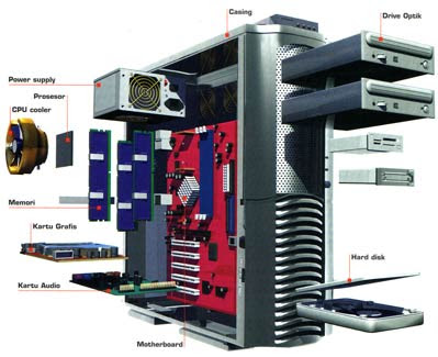
1. Processor, mainboard, memory, processor, fan heatsink, VGA card, hard disk, keyboard, mouse, optical drive, power supply, casing, monitor.
2. Toolkits.
3. Stabilizers.
4. Mainboard manual.

Steps before installing hardware components
To avoid damage to computer equipment, it is prohibited to install or remove components from the mainboard such as: RAM, VGA Card, power supply connector, jumper settings and objects made of metal on the mainboard while the power supply is still on.
Processor
1. Prepare the processor socket on the mainboard by first opening or pulling the socket stem upwards so that it doesn't lock.
2. Place the processor in the socket according to the dot or slanted side of the processor in the same position as the socket correctly and tightly.
3. Lock the processor socket again by lowering the socket handle until it is locked properly.
4. Apply sufficient paste to the top of the processor where the heatsink will be installed.
5. Install the heatsink fan on top of the processor correctly and keep it locked properly so that it doesn't shake or appear to be coming off again.
6. Connect the heatsink fan power connector to the power socket on the mainboard.
7. Make sure the processor and heatsink are installed correctly and well. Install the nuts and bolts on each side of the heatsink.
Memory
1. Adjust the gap at the bottom of the RAM with the slot gap on the mainboard.
2. Install the RAM into the slot on the mainboard by holding one side of the part with your right hand and the other side with your left hand.
3. Make sure the clips on both sides of the white RAM slot on the mainboard are open or moved to the side.
4. Plug the RAM into the memory slot on the mainboard by pressing the two sides that are held slowly and carefully so that the clips on the two sides of the memory slot on the mainboard are locked properly and properly.
5. Make sure the RAM is installed properly and correctly.
Mainboard
1. Open the right and left casing covers.
2. Make sure the left side of the casing or the empty part (there is no iron plate or sheet covering it like the right side of the casing) is facing up.
3. Attach the plastic hook or bolt that manufacturers usually provide in the hole in the iron plate in the casing.
4. Insert the mainboard slowly and carefully from the top of the open side into the mainboard. Make sure the position of the small hole meets the installed plastic latch while pressing gently until it locks so that the position of the mainboard fits onto the metal sheet inside the casing correctly and well.
5. To avoid shifting of the mainboard inside the casing, it is best that every hole in the mainboard that is still empty be bolted and locked properly on the iron plate of the casing.
6. Make sure the mainboard is installed properly and does not shake.
PSU / POWER SUPPLY
1. Stand the casing in position first.
2. Install the power supply from the inside in a position behind the casing..
3. Make sure the position of the power supply is correct and locked or resting on the back of the casing.
4. Make sure the power supply bolt holes meet the bolt holes on the casing so that several bolts can be installed and locked properly.
5. Make sure the power supply is installed properly and is not shaking.
VGA CARD
1. Make sure the case remains in the sleeping position.
2. The AGP type VGA card is plugged into the AGP type slot available on the mainboard. The PCIe VGA Card is installed in the PCIe type slot on the mainboard. First, adjust the type of VGA Card that will be used.
3. Install the VGA Card carefully. Perpendicular to the plane of the mainboard and make sure the position of the gap on the card matches and matches the slot gap on the mainboard.
4. Lock the VGA Card so it doesn't come loose by installing the bolt at the top of the VGA Card to the back of the casing that is provided.
5. For analog monitors, a monitor connector can be added so that the monitor can be used according to specifications, without having to replace it with a new monitor.
6. Make sure the VGA Card is installed in the correct slot properly and does not shake or come off.
CARD ADD ON
1. Installing additional equipment or add-on cards on the mainboard is the same as installing a VGA card on the mainboard, just adjust the slot used by the add-on card.
2. Usually the add-on card is installed in a PCI type slot on the mainboard, such as a TV tuner, modem, sound card, LAN card and so on.
HARD DISK & OPTICAL DRIVE
1. Make sure the casing remains in a standing position.
2. Instead of bolts, install plastic hooks that will connect the hard disk to the casing. Install the hard disk with the connector and interface (SATA) facing inward according to the mount on the casing. When using bolts, don't forget to tighten the bolts.
3. Install the optical drive in the existing position on the outer front of the casing, by first opening the plastic plate cover on the front of the casing.
4. Make sure the hard disk and optical drive are installed properly and do not wobble.
MAINBOARD POWER CABLE
1. Connect the mainboard power cable to the power supply with the power socket (usually white), with the characteristic that it has a separate connector or is different from the existing power cable connector. The characteristic of this cable connector on an ATX power supply is that the two regular power connector parts become one part and the middle part has a lock. Installation is done by connecting the lock on the power cable connector and the lock on the power slot on the mainboard. If it is reversed or incorrect, the connector will not fit into the power slot on the mainboard. So, don't be afraid to make a mistake.
2. Make sure the power supply cable connector is installed in the correct position so that it is not loose.
POWER INTERFACE CABLE
1. For hard disks, the SATA interface has a power cable and interface that is different from the usual power cable and IDE interface.
2. Attach the SATA power cable from the thin and small power supply (usually black) to the SATA hard disk connector correctly and properly. If something goes wrong or is reversed, the connector usually won't fit.
3. Attach the SATA hard disk interface cable with one connector paired with the primary connector slot on the mainboard and the other connector paired with the SATA interface slot on the hard disk. This SATA interface cable is thin and smaller than the wide and large IDE cable.
4. Make sure the power cable and interface cable are installed correctly and well so that nothing is loose.
OPTICAL DRIVE AND FAN POWER CABLES
1. Most optical drives still use ordinary power cables and IDE interface cables.
2. Attach the power supply cable to the optical drive connector slot in the correct and correct position. If it is wrong, the power cable connector will not fit into the connector slot on the optical drive.
3. Attach one side of the IDE interface cable to the secondary IDE connector slot on the mainboard in the correct and good position. If it is reversed, the connector will not insert and attach. Then attach the other side to the connector on the optical drive with the position of the red line on the IDE interface cable meeting the red side of the installed power supply cable. If an error occurs or is reversed during installation, this interface cable will not be inserted and installed properly.
GROUP PINS
1. Before installing, it is best to position the casing back in a sleeping position, which will make it easier to install the pingroup connector cable.
2. Some casings are equipped with indicator light cables and speaker cables that simply attach to the pins (legs) on the mainboard.
3. For lay people, installation of this connector cable must be done according to the mainboard manual, because some mainboards have different pin locations.
4. Attach the pingroup cables to the mainboard according to their respective functions. For example, the reset connecting connector is attached to the reset pin on the mainboard, the LED connector is attached to the LED pin on the mainboard and so on. Adjust to the existing mainboard manual.
5. Make sure the pingroup connector cable is installed correctly and well without any installation errors.
COMPLETE THE HARDWARE INSTALLATION
1. Make sure all the components in the casing are installed properly and correctly in their respective positions.
2. Make sure all power cables and interface cables are installed on the components in the correct condition and nothing is loose.
3. Close both parts of the casing again.
MONITORS
1. Attach the connector or data cable from the monitor to the VGA Card socket on the back of the casing.
2. Connect the monitor power cable to the power supply connector or electric stabilizer.
KEYBOARD AND MOUSE
1. Attach the purple PS/2 keyboard connector to the purple PS/2 slot on the back of the casing.
2. Also, attach the green PS/2 mouse connector to the back of the casing where the PS/2 slot is green.


Tidak ada komentar:
Tidak ada yang sempurna, begitu pula dengan saya, masukkan anda begitu berarti bagi perkembangan Blog ini dan diri pribadi saya...jangan pake spam...pokoknya NO SARA, NO SEX, NO ANARKI, NO POLITIK!!! Piss and luv.... Terimakasih